|
5
|
|
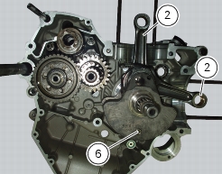
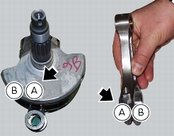
Remove the alternator-side crankcase cover and the alternator assembly
|
|


|
2
|
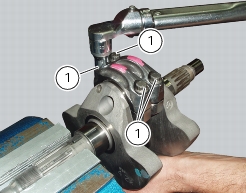
now carry out a second tightening stage applying a torque of 35 Nm on each screw;
|
|
3
|
now tighten each screw, reading the angle of rotation, to 70 Nm, checking that the final angle is between 55° and 75°.
|

|
Refit the alternator-side crankcase cover and alternator assembly
|
|