6.2 -
1
2
3
4
5
6
7
8
9
10
11
12
13
14
15
16
17
18
19
Spare parts catalogue
Important
Bold reference numbers in this section identify parts not shown in the figures alongside the text, but which can be found in the exploded view diagram.
Removal of the clutch-side crankcase cover
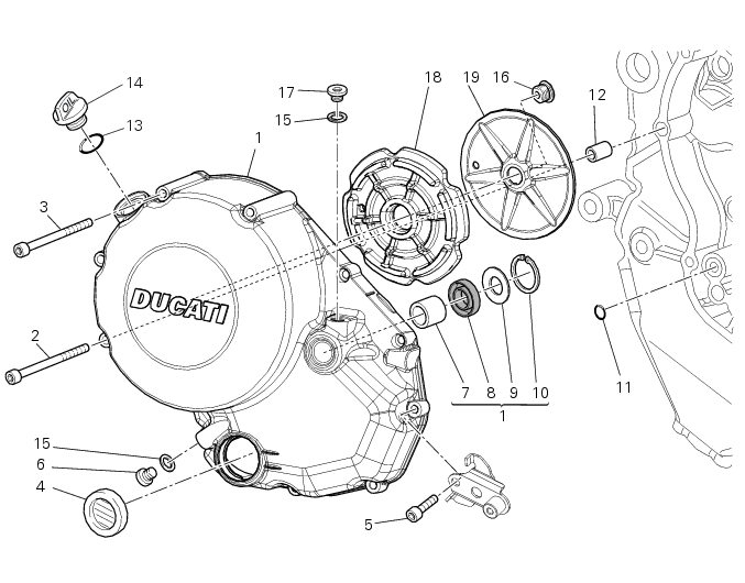
Unscrew the screws (2), (3) and (5) securing the clutch-side crankcase cover (1).
Tap around the edge of the cover with a plastic mallet to detach it from the crankcase half.
Remove the clutch cover (1) paying attention to the centring bushing (12).
Check the condition of the centring bushing (12) and replace if deformed.
Disassembly of the clutch-side crankcase cover
Remove the plug (14) and its O-ring (13), the plug (17) and its O-ring (15) from the cover.
Undo the fixing screw (16) of the inner cover (19).
Remove the inner cover (19) and sound-proofing panel (18).
Remove the circlip (10) and withdraw the shim (9) and the sealing ring (8).
The drilled bush (7) is mounted to the cover by a forced interference fit. Remove it using a suitable puller.
Inspect the sealing ring (8) and renew it if necessary.
Reassembly of the clutch-side crankcase cover
Fit the plug (14) and the gasket (13). Fit the plug (17) and the gasket (15).
If the bush has been replaced, fully seat the new bush (7) in the slot in the cover using a suitable drift and a press.
If the sealing ring (8) needs to be renewed, fit the new seal into the crankcase cover, positioning it so the side without a spring is facing the circlip (10).
Before fitting, check that the edges of the circlip groove show no sign of burrs which might otherwise damage the sealing ring.
Then fit the shim (9) and the circlip (10).
Important
In order for the sealing ring (8) to function correctly, it must have an assembly clearance that allows the circlip (10) to rotate.
 
Position the sound-proofing panel (18) inside the clutch-side crankcase cover (1), aligning it with the pin (D) as shown in the figure.
Position the inner cover (19) on the panel (18), aligning it with the pin (D).
Apply the recommended threadlocker to the screw (16).
Tighten the retaining screw (16) to a torque of 24 Nm (Min. 22 Nm - Max. 26 Nm) (Sect. 3 - 3, Engine torque settings).
Refitting the clutch-side crankcase cover
Clean and degrease mating surfaces on the clutch-side crankcase half cover and crankcase and ensure that locating bush (12) and the O-ring (11), located in correspondence with the oil way, are installed in the crankcase.
Apply an even, regular bead of DUCATI liquid gasket (A) on the mating surface of the crankcase half and around all holes.
Fit the cover assembly (1) to the crankcase half and insert the retaining screws.
Apply recommended threadlocker to the screws (2), (3) and (5).
Lock the screws (2), (3) and (5) to a torque of 10 Nm (Min. 9 Nm - Max. 11 Nm) (Sect. 3 - 3, Engine torque settings) in a cross-pattern sequence.


1