|
2
|
|
8
|
|
9
|
|
11
|
|
12
|
|
13
|
|
18
|
|
19
|
|
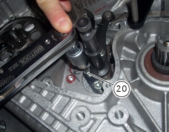
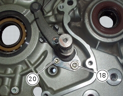
20
|
|
23
|
|
24
|
|
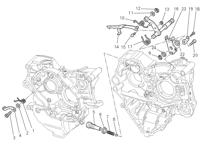
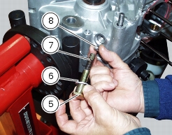
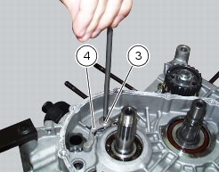
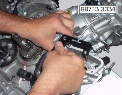
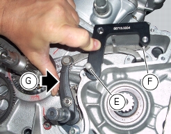
Remove the alternator-side crankcase cover and flywheel-alternator assembly
|

|
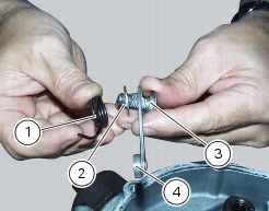
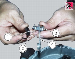
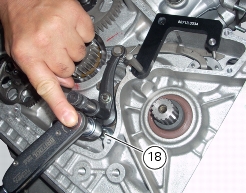
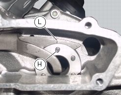
Refit the flywheel/alternator assembly. and alternator side crankcase cover
|
|