3.3 -
1
2
3
4
5
6
7
8
9
10
11
12
13
14
15
16
17
18
 Spare parts catalogue
Important
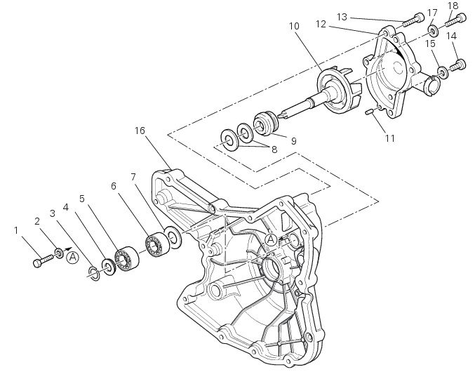
Bold reference numbers in this section identify parts not shown in the figures alongside the text, but which can be found in the exploded view diagram.
Removal of the water pump
Note
For clarity, the figures show the engine removed from the frame.
 
Unscrew and remove the water pump cover (12) fixing screws (13) and (18) to the alternator cover (16).
Remove the water pump cover (12).
Clean the pump housing of any scale. Check the bearings wear by turning the impeller shaft (10); in case of excessive clearance, it is necessary to replace them by operating as follows.
Remove the circlip (3) on the impeller shaft and the washer (4) located below it.
Slide off the rotor (10) with the sealing ring (9) from the outside.
Recover the ceramic washer (A) and sealing ring (B) located on the inner side.
Undo and remove the screws (1) with the washer (2).
Working from the impeller side, use a suitable drift to press on the inner race of end bearing (5) until it can be extracted from the cover.
Use the same technique to remove the other bearing (6).
Working from the inside of the cover, remove the counterface (8) of the mechanic seal (9).
Remove the inner spacer (7).
Check the condition of the components of the mechanical seal: there should be no signs of deformation, cracking, or excessive wear. In the case of damage, both components must be renewed.
Refitting the water pump
Clean the seat in the cover, any parts you intend to reuse, and the impeller shaft. Lubricate with engine oil and refit as follows.
Using pad with code 88713.0869 fit the new mechanic seal (9) on the impeller shaft.
Working from the inside of the cover, fit the inner spacer (7) with its square edge (A) facing outwards.
Using a suitable drift that bears on the outer race, drive home the bearing (6) against the spacer (7) with the shield side (B) facing the cover.
Install the other bearing (5) against the previous one.
Apply recommended threadlocker.
Fit the two screws (1) with washer (2), and tighten them to a torque of 10 Nm (Min. 9 Nm - Max. 11 Nm) (Sect. 3 - 3, Engine torque settings).
Turn over the cover and, using the tool code 88713.0870, install the counterface (8), located as shown in figure, until it stops against the spacer (7).
Fit the sealing ring (B) and the ceramic washer (A).
Insert the impeller shaft (10) with the mechanic seal (9) and turn the cover over.
Fit the spacer (4), positioned as shown in the cross-sectional view, and lock the assembly in place with circlip (3).
Rotate the impeller (10) and make sure it turns smoothly without sticking.
Clean the mating surfaces thoroughly on the pump cover and on the alternator-side crankcase cover.
Apply a bead of liquid gasket to the water pump cover (12) as shown in the figure.
Fit the locating dowels (11) and position the pump cover (12) on the alternator-side crankcase cover.
Insert the fixing screws (13) and (18) of the cover.
Tighten the screws (13) to a torque of 10 Nm (Min. 9 Nm - Max. 11 Nm) (Sect. 3 - 3, Engine torque settings).
Tighten the screw (18) to a torque of 13.5 Nm (Min. 12.5 Nm - Max. 14.5 Nm) (Sect. 3 - 3, Engine torque settings).
Refit the components removed in the procedure.
 
 
1