8.2 -
1
2
3
4
5
6
7
8
9
10
11
12
13
14
15
16
17
18
19
 Spare parts catalogue
Important
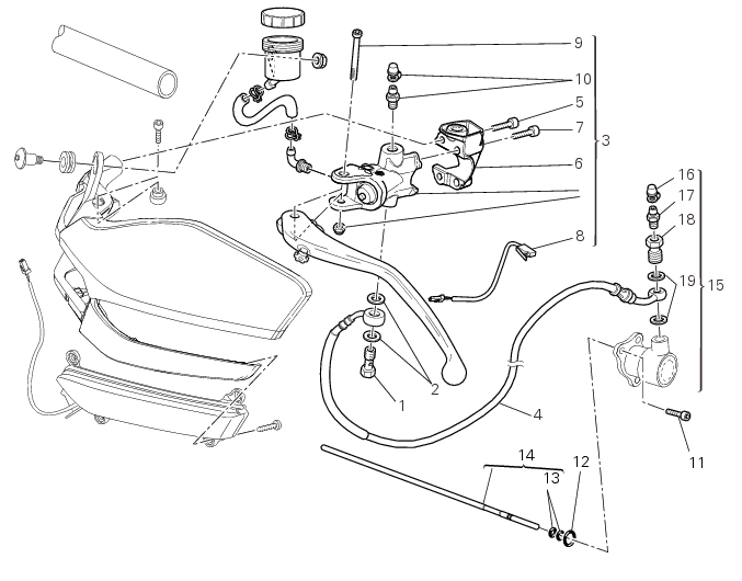
Bold reference numbers in this section identify parts not shown in the figures alongside the text, but which can be found in the exploded view diagram.
Removal of the clutch master cylinder assembly
Warning
The clutch master cylinder manufacturer advises against servicing of the clutch master cylinder (1) due to the safety-critical nature of this component. Incorrect overhaul of this component could endanger rider safety.
 
Maintenance operations of the master cylinder are limited to replacing the following parts: control lever, reservoir unit, and master cylinder fasteners.
 
Loosen the special screw (1) by collecting the seals (2), to release the clutch master cylinder assembly (3) from the clutch control pipe (4).
Undo the fixing screws (5) of the mounting u-bolt (6) and then remove the clutch pump unit (3) from the handlebar.
Refer to the exploded view at the beginning of this section for indications on disassembly and replacement of the master cylinder components.
Refitting the clutch master cylinder assembly
Fit the clutch master cylinder assembly (3) onto left side of handlebar, by inserting the handlebar centring pin (A) into hole (B) of the clutch master cylinder control.
Couple terminal (6) to the clutch master cylinder control and fix them with the screws (5).
Tighten the fixing screws (5) to a torque of 10 Nm ± 10% (Sect. 3 - 3, Frame torque settings) following the sequence 1-2-1 start­ing from the upper screw.
Locate the pipe (4) and seals (2) on the master cylinder assembly (3) and secure it with the special screw (1), without tightening it.
Warning
An incorrectly positioned hose can cause clutch faults and interfere with moving parts.
 
For the positioning of the clutch hose (6) and retaining clips, see the illustration at the end of this section.
Tighten the special screw (1) to the torque of 23 Nm ± 10% (Sect. 3 - 3, Frame torque settings).
 
Removal of the clutch transmission unit
Warning
The manufacturer of the clutch transmission unit (15) advises against servicing of its internal parts due to the safety-critical nature of this component.
Incorrect overhaul of these critical safety components can endanger rider and passenger safety.
The only components that should be renewed are the complete clutch transmission unit, the bleed valve, the seals and the com­plete clutch pushrod assembly.
 
Remove the clamps (A) and release the clutch tube (4) from the side stand wire (B).
Loosen the screws (11) and slide off the clutch transmission unit (15) paying attention to the O-ring (12) positioned on its inside.
Remove the dust gaiter (16) and the bleed valve (17) and unscrew the screw (18), taking care to recover the gaskets (19): the unit (15) is now disconnected from the pipe (4).
Push in the piston to force out all the fluid from inside the cap.
At this point, it is possible to slide also the clutch gear rod (14). Check the wear state of the two O-rings (13) and replace them, if necessary.
Note
If the two O-rings (13) need be replaced, it is necessary to replace also the O-ring (12) of the unit (15).
Refitting the clutch transmission unit
Note
If the clutch pushrod (14) is replaced, it is necessary also replace the two O-ring (13) and (12) of the unit (15).
 
Grease and refit the clutch pushrod (14) with the two O-rings (13).
Lubricate the gasket (12) and locate it along with the transmission unit (15) in the crankcase.
Position pipe (4) on the clutch transmission unit (15).
Position the two seals (19) and tighten the screw (18) to a torque of 23 Nm ± 10% (Sect. 3 - 3, Frame torque settings).
Refit the bleed valve (17) and the dust gaiter (16).
To position the pipe retaining clamps (4) refer to the table on the following page.
 
Fit the transmission unit (15) on the crankcase and tighten the screws (11) to a torque of 10 Nm ± 10% (Sect. 3 - 3, Frame torque settings).
Strip the clutch pipe (4) to the side stand wire (B) and insert this last one into the breaker (C).
 
 
Positioning of the clutch hose
 
 
1