8.1 -
1
2
3
4
5
6
7
8
9
10
11
12
13
14
15
16
17
18
19
20
21
22
23
24
25
26
27
28
 Spare parts catalogue
Important
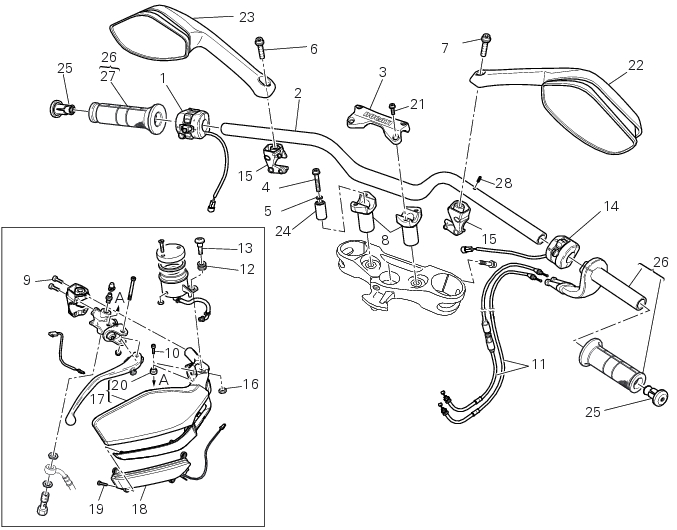
Bold reference numbers in this section identify parts not shown in the figures alongside the text, but which can be found in the exploded view diagram.
Removal of the rear-view mirrors
Undo the screws (6) and (7) and remove the rear-view mirrors (23) and (22).
Warning
The screw (6) of the left mirror has a left-handed thread.
Refitting the rear-view mirrors
Insert the screws (6) and (7) in the rear-view mirrors (23) and (22).
Insert the rear-view mirrors (23) and (22) in the U-bolts (15).
Tighten the screws (6) and (7) to a torque of 40 Nm ± 10% (Sect. 3 - 3, Frame torque settings).
Removing of the hand guards
The removal procedure is the same for both hand guards. Find below the description for the RH hand guard (17).
Remove the rear-view mirrors as indicated in paragraph “Removal of the rear-view mirrors“ of this section.
Loosen and remove the fixing screws (9) of the hand guard to the terminal.
Loosen and remove the fixing screw (13), collect the vibration damper mount (12).
Undo the screw (10) and collect the spacer (20).
Disconnect the connector (D) of the front arrow (Sec. 6 - 1, Routing of wiring on frame) and remove the complete right hand guard.
If necessary, disassemble it undoing and removing the screws (19).
Refitting the hand guards
For refitting the hand guards follow the reverse order; remember to fix the screws (19) to a torque 0.45 Nm ± 10%, the screw (13) to a torque of 2 Nm ± 10%, the screws (9) to a torque of 5 Nm ± 10% (Sect. 3 - 3, Frame torque settings).
Tighten the screw (10) to a torque of 10 Nm ± 10% (Sect. 3 - 3, Frame torque settings).
Refit the rear-view mirrors as indicated in section “Refitting the rear-view mirrors“ of this section.
 
Removal of the handlebar
Remove the RH switch (G), by disconnecting the connector of the main wiring (Sect. 6 - 1, Routing of wiring on frame) and loos­ening the screws (H).
Remove the LH switch (L), by disconnecting the connector of the main wiring (Sect. 6 - 1, Routing of wiring on frame) and loos­ening the screws (M).
Undo and remove the fixing screws (21) of the U-bolt (3).
Remove the upper u-bolt (3).
Remove the handlebar (2) from its seat on the steering head.
To remove the grips (26), refer to the exploded view at the beginning of this chapter.
Undo the screws (4) and remove the stud bolts (8) of the steering head; recover the washers (5).
Refitting the handlebar
If the spacers (24) were removed from the steering head, lubricate with silicone spray.
Seat the spacers (24) in the bores (A) in the steering head, orienting them as indicated.
On completion of the operation, clean all excess lubricant from the components.
Apply the recommended threadlocker to the threads and undersides of the screws heads (4).
Insert the screws (4) with the washers (5) in the stud bolts (8).
Locate the stud bolts (8) on the steering head.
Tighten the screws (4) to the torque of 25 Nm ± 10% (Sect. 3 - 3, Frame torque settings).
Position the handlebar (2) in its seat on the stud bolts (8).
The bolted joints points (F) on the handlebar must be equidistant from the stud bolts (8) and aligned with the plane of the same stub bolts.
Apply recommended grease to the screws (21).
Refit the U-bolt (3) by starting the screws (21).
Tighten the screws (21)to a torque of 25 Nm ± 5% (Sect. 3 - 3, Frame torque settings), following the sequence 1-2-3-4-3, as in­dicated.
Refit the grips (26) referring to the exploded view at the beginning of this chapter.
Refit the LH switch (L) by tightening the screws (M) to a torque of 1.3 Nm ± 10% (Sect. 3 - 3, Frame torque settings) and con­necting the connector to the main wiring (Sect. 6 - 1, Routing of wiring on frame).
Refit the RH switch (G) by tightening the screws (H) to a torque of 1.3 Nm ± 10% (Sect. 3 - 3, Frame torque settings) and con­necting the connector to the main wiring (Sect. 6 - 1, Routing of wiring on frame).
 
Warning
When the handlebar and all its elements are fitted, check that by steering completely the handlebar the adjusting knob (A) of the headlight fairing Plexiglass in the fully up position (i.e. with headlight fairing totally up) does not interfere with any part of the motorcycle.
In case of malfunction, i.e. if the Plexiglass knob touches any part of the motorcycle (such as the handlebar), it is necessary to work on the stop adjusters (B) and the relevant nuts (C) until the bike set-up is perfect with the handlebar steering with no contact with the knob. After performing this check, make sure that when the handlebar is fully turned to the left, the clutch master cyl­inder filler does not interfere with the fuel tank, and when the handlebar is fully steered to the right, the twistgrip does not touch the fuel tank.
Adjusting the throttle cable
To operate on the set screws of the throttle grip cables, consult Sec. 4 - 3, Adjusting the throttle cable.
Removal of the throttle twistgrip
Remove the end plug (25) from the handlebar.
Peel back the rubber sleeve (A) protecting the throttle control cables.
Undo the screws (B) of the throttle grip (26) and open the command.
Disconnect the throttle grip cables (11) by unhooking the cable ends (C) from their seats.
Remove the throttle twistgrip (26) from the handlebar.
Note
To replace the throttle grip cables, it is necessary to remove it from the throttle body (Sec. 8 - 6, Removal the airbox and throttle body).
Replacement throttle cables are supplied complete with adjusters.
Refitting the throttle twistgrip
Lubricate the ends of the throttle grip cables (11) and the twistgrip race with the recommended grease.
The closing cable (11) features a writing on the yellow tube, whereas the opening one (11) features such writing on the white tube.
To refit the throttle control components, proceed in inverse order to the removal procedure, making sure that the twistgrip hous­ings locate in the reference hole in the handlebar.
Tighten the screws (B) of throttle twistgrip (26) to a torque of 10 Nm ± 10% (Sect. 3 - 3, Frame torque settings).
Note
Refer to the tables on the next page for correct routing of the throttle grip cable.
Routing the throttle cables
1