8 -
1
2
3
4
5
6
7
8
9
10
11
12
13
14
15
16
17
18
19
20
21
22
23
24
25
26
27
28
29
30
31
32
 Spare parts catalogue
Important
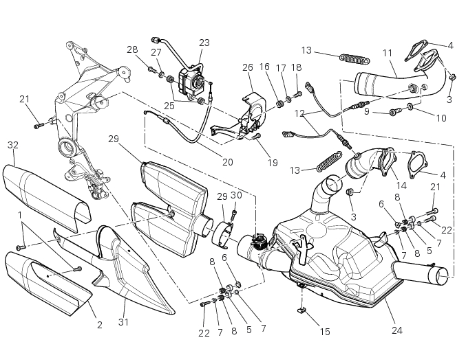
Bold reference numbers in this section identify parts not shown in the figures alongside the text, but which can be found in the exploded view diagram.
Removal of the exhaust system
Undo and remove the four upper fixing screws (1).
Remove the protection group (2) (31) and (32).
Turn the exhaust valve pulley (A) to facilitate the throttle cable (20) output.
Slide the throttle cable (20) from the pulley (A).
Undo the nut (C).
Release the control cable (20) from the plate (B).
Remove the two fixing springs (13).
Hold the catalytic converter (24) and operating on the left side of the vehicle, undo and remove the screw (22).
On the right side, undo and remove the screw (22).
Remove the catalytic converter (24)
Undo and remove the horizontal cylinder lambda probe (12).
Undo and remove the three fixing nuts (3) and remove the horizontal manifold (11) with the gasket (4).
Undo and remove the vertical cylinder lambda probe (12).
Undo and remove the three fixing nuts (3) and remove the manifold (14) with the gasket (4).
Refitting the exhaust system
Position the vertical exhaust manifold (14) on the vertical cylinder head with the gasket (4).
Tighten the fixing nuts (3) to a torque of 10 Nm ±10% (Sect. 3 - 3, Frame torque settings).
If removed, tighten the vertical lambda sensor (12) to a torque of 24.5 Nm ± 10% (Sect. 3 - 3, Frame torque settings).
Position the horizontal exhaust manifold (11) on the horizontal cylinder head with the gasket (4).
Tighten the fixing nuts (3) to a torque of 10 Nm ±10% (Sect. 3 - 3, Frame torque settings).
If removed, tighten the horizontal lambda sensor (12) to a torque of 24.5 Nm ± 10% (Sect. 3 - 3, Frame torque settings).
Position the catalytic converter (24) and operating on the left side of the vehicle, insert the screw (22).
Holding the catalytic converter, operating on the right side of the vehicle, insert the screw (22).
Position the two fixing springs (13).
Tighten the two retaining screws (22) to a torque of 10 Nm ± 10% (Sect. 3 - 3, Frame torque settings).
Position the control cable (20) in the plate (B).
Turn the exhaust valve pulley (A) to facilitate the throttle grip cable (20) introduction.
Tighten the fixing nut (C) to a torque of 2.5 Nm ± 10% (Sect. 3 - 3, Frame torque settings).
Position the protection group (2), (31) and (32).
Tighten the four retaining screws (1):
A
B
If removed, fit the copper washers (10) to the plugs (9), start the plugs into the vertical (14) and horizontal (11) head exhaust man­ifolds and tighten them to the torque of 25 Nm± 10% (Sect. 3 - 3, Frame torque settings).
 
1