2.1 -
1
2
3
4
5
6
7
8
9
10
11
12
13
14
15
16
17
 Spare parts catalogue
Important
Bold reference numbers in this section identify parts not shown in the figures alongside the text, but which can be found in the exploded view diagram.
Removal of the oil pump
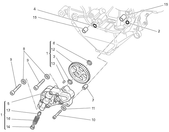
Undo and remove the screws (9) and (10) securing the pump assembly.
Remove the oil pump assembly (1) and extract the O-rings (2) and (4) from the crankcase half together with two locating bushes (15).
Disassembly of the oil pump
Hold the oil pump (1) in a vice taking care not to damage the drive gear (12).
Warning
Make sure that vice jaws are faced with soft material.
 
Remove the plug (14) and extract the spring (16) and by-pass valve (17).
Check the condition of the above components.
Remove the circlip (6) and withdraw the pump drive gear (12).
Reassembly of the oil pump
Check that the circlip (3) and tongue (13) are present on the pump.
Fit the pump drive gear (12) on to the oil pump and secure it by installing the circlip (6) in its groove.
Insert in the pump the by-pass valve (17), the spring (16) and screw and tighten the plug (14) to the specified torque of 17 Nm (Min.15 Nm - Max. 19 Nm) (Sect. 3 - 3, Engine torque settings) by applying a threadlocker of medium strength.
Refitting the oil pump
If removed, apply specific threadlocker on the bushing (7) and screw it in the crankcase half, observing the height.
Position the reference bushings (15) and the oil sealing O-rings (2) and (4) according to the crankcase lubrication channels.
Position the oil pump on the crankcase and tighten screws (9) to a torque of 26 Nm (Min. 23 Nm - Max. 29 Nm) and (10) to a torque of 10 Nm (Min. 9 Nm - Max. 11 Nm) (Sect. 3 - 3, Engine torque settings).
Check the gear clearance with the driving pinion by fixing a dial gauge (A), equipped with the appropriate traces, to the crankcase half.
Position the dial gauge stylus on one tooth of oil pump gear and set the gauge to zero in this position.
Move the gear slightly to measure the backlash; take four readings in diametrically opposed positions of the gear.
The clearance should be 0.10 mm.
 
1